Installing and using the DFCv4 without using AFR.
Without the availability and display of an AFR sensor it is more difficult to determine what AFR levels the D-jet engine is running at during variating driving conditions. However, there are a few options that can be undertaken to gain a better understanding of what AFR range the D-jet engine is running under when using the DFCv4 – without the any AFR sensor input.
Option 1: Adjust the DJ-Base T1 to obtain a desired AFR level at a running Garage -Idle (GI-RPM 2000-2300) condition using a CO sensor inserted into the exhaust pipe. The O2 sensor results during normal engine idle (800-1200 RPM – while the TPS idle switch is closed) can also be used to set the desired AFR by adjusting the ECU Idle-Mixture control knob.
However, before starting any CO based tuning execute step1 describe below for Option2 to reset the DFCv4 to a neutral state matching the existing D-jet engine condition.
The link to the whitepaper CO-to AFR shows how the CO to AFR ratio is very close to being linear down to an AFR ratio of 14.25:1, hereafter the CO value approaches zero at the AFR level 14.75 – as also depicted below.
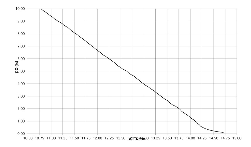
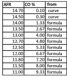
Such linear CO-to-AFR relationship can also be reduced to a formula for finding what the CO value will be for any desired AFR value between 10.00 and 14.25 as follows:
CO = (14.5 – AFR) / 0.375
The table below shows how the calculated CO values would be for specific AFR values 14.00 and below. The two CO values for AFR values 14.5 and 14.7 are derived from the CO-to-AFR graph shown above.
Here is a link to another more extensive table preciously published for MG-car-engine-tuning.
If a full range (0.10% to 9.0%) CO sensor is difficult to find these days, a more modern CO sensor measuring less than 1.5% CO can be use to set the AFR level to the 14.5 to 14.7 range.
Option 2: May be chosen when the existing D-jet engine is operating at a desirable close-to-factory fuel ratio condition. In such cases, the T1 DJ-base is adjusted to obtain an MPS-10 value to match the MPS-10 value measured with the AFR-control slide switch in the OFF position.
After step1 and step2 activities have been completed, the AFR Adj (P1) at the DFC front can be turned in richer or leaner directions while driving to observe how the engine is performing at various fuel mixture settings. Any different setting from the well-known past conditions (before installing the DFC) can at any time be reversed by sliding the AFR Control into the OFF (center) position.
Step1: Adjusting the DFC to a neutral condition – matching the existing D-jet ECU condition – first when engine is not running – later repeated with engine running:
- connect a voltmeter to the MPS-10 (pin3) monitor interface.
- switch the AFR-Control switch to the OFF position and turn on the ignition – first time without starting the engine.
- make-a-note of what the MPS-10 signal voltage is.
- preset the AFR Adj pot-meter to the top position for subsequent limited (-5%) lean adjustments – or preset to the 10 o’clock position for more extensive (-15%) lean AFR adjustments. Alternatively, disable the AFR Adj pot-meter switching the rear Adj on/off switch to the up-position.
- slide the AFR-Control switch to the MAN position and observe the MPS-10 signal level may be changing.
- adjust the DJ-base T1 to obtain an MPS-10 voltage identical (or veery close to) the MPS-10 value obtained at the OFF position.
- slide the AFR-Control switch back to the OFF position and observe the MPS-10 signal is now returning to the initially noted value.
- make sure nothing is connected to the AFR input (pin4) of the DFC AFR interface or the AFR sense (pin1) of the DFC monitoring interface.
- slide the AFR-Control switch to the FB position and observe the MPS-10 signal level may be changing.
- adjust the AFR-base T2 to obtain an MPS-10 voltage identical (or close to) the initial MPS-10 value noted at the OFF position.
- slide the AFR-Control switch back to the OFF position and observe the MPS-10 signal is now returning to the initially noted value.
- end of step1 — the DFCv4 is now configured to a neutral condition where the DFC will make no (or very little difference) to the engine D-jet fuel mixture level when the AFR-Control switch is cycled between the OFF, MAN or FB positions.
Step2: Repeating the DJ-base and AFR-base adjustments – this time with a warmed-up engine running at the GI-RPM (1800 to 2200) range.
- slide the AFR-Control switch to the OFF position and start the engine.
- let the engine run until it is fully warmed up and the starting RPM level has settled into the normal idle RPM level.
- insert a feeler-gauge (16-22Mil) at the throttle stop-screw to obtain a steady GI-RPM level in the 1800 to 2200 range.
- now repeat all Step1 actions – but this time with the engine running at the GI-RPM level.
- the DFCv4 is now set in a neutral state matching the running engine condition, where the DFC will make no (or very little difference) in the D-jet fuel mixture when the AFR-Control switch is moved between the OFF, MAN or FB positions.
- remove the 18-20 MIL feeler gauge and instead try to maintain a constant RPM condition in the 2000 to 3000 range by holding the accelerator in a fixed position.
- adjust the front AFR Adj (P1) pot-meter (slowly) into the rich-mixture as well as into the lean-mixture ranges while maintaining the constant RPM condition.
- observe how the RPM level appears to increase somewhat as the mixture is enriched – while the RPM level will decrease very little when adjusting into the lean mixture range.
- end of step2 — the DFCv4 is now configured to a neutral running condition where the DFC will make no (or very little difference) to the engine D-jet operation – as long as the AFR Adj pot-meter is returned to the initially set (top or 10’clock) position.
When driving the car, it is evident that the engine power increases as the AFR Adj is turned towards a rich position. But it is less evident that the engine loses power when turning the AFR Adj into a leaner position. Only when the mixture is leaned out significantly the engine will “stumble” and possibly also “ping” when accelerating from a full (or rolling) stop. I such cases the AFR level typically reaches into the 17-18 AFR range.
Warning, driving the car continuously in a highly leaned-out mixture condition (15-17 AFR range) will increase the exhaust temperature and possibly cause unwanted damage to the engine and exhaust system.
Option 3: Adjust the DJ-base signal to achieve a desired AFR level using the GI-AFR tuning procedure described below.
Previous testing using ver4 DFC has revealed that the AFR level is variating closely in a linear relation with a changing MPS-10 signal level.
However, this observation only holds true under the following conditions:
A: The warmed-up engine is running (in neutral gear) at the 1800 to 2600 RPM range, also called “Garage-Idle” (GI) state, where changes to the Engine Speed Compensation (SC) is minimal.
B: The intake air rate remains constant (i.e. a small throttle opening remains constant).
C: Air and coolant temperatures remain constant (engine already warmed up).
As long as the above conditions are maintained, the AFR level will be enriched and the RPM level will increase, when the AFR-10 signal is adjusted downward (and vice versa).
The max-RPM level (max torch) condition will be achieved when the AFR level is reaching 11.8 :1– depending slightly on fuel octane mixture.
Considering the above, the procedural steps below can be used to determine how the MPS-10 signal level can be adjusted to obtain a desired AFR level as the GI-PPM is returning towards the initially set GI-RPM (1800-2200) level.
After a desired AFR level for the GI-RPM (1800-2200) has been reached (and test results saved) the AFR level for the normal engine idle-RPM (800-1200) range can also be set – but this time using the ECU idle mixture control knob.
After a close-to-factory D-jet engine GI-AFR setting has been established, using the procedures below, the engine AFR levels at various other driving conditions should be close to what has already been described in original D-Jet. documentation.
>> GI-AFR tuning for DFCv4 MAN operation mode
The DJ-Base Trim (T1) can be used to set a desired GI-AFR level without using an AFR sensor as follows:
–First execute step1 described under Option1 to set the DFC in a well-known (neutral) condition.
– Connect a voltmeter to the MPS-10 signal (pin3) and another (preferable analog) voltmeter to the RPM signal (pin2) of the 6-pin DFC Monitor & Logging interface.
– Start the already warmed-up engine and insert a 16-22 MIL feeler gauge at the throttle-stop screw to maintain a steady 1800-2200 RPM GI running condition.
– Adjust the T1 counter-clockwise and observe how the initial MPS-10 value (range 2.4V to 2.5V) is decreasing (while RPM level is increasing) as the T1 is steadily turned into richer positions – and vice versa if the T1 is turned clockwise.
– Continue adjusting the T1 to obtain the max-power rich position where the maximum RPM level is observed (analog voltmeter is peaking). Continuing into an even richer position will cause the RPM level to drop.
Make a Note of what the MPS-10 voltage (“V-max-AFR”) is at this max-power (highest torch) setting. Existing documentation for gasoline powered internal combustion engines concludes that the AFR level will be 11.8:1 when max torch (in this case highest GI-RPM value) is obtained.
– Hereafter, the T1 trim should be turned steadily clockwise to obtain a desirable GI-AFR level to be used under daily driving conditions. As the MPS-10 signal level is now observed to be increasing the AFR level will also be increasing.
– Previous testing of the DFC (with the help of an active AFR sensor display) indicates that the MPS-10 signal is increasing by 7.5% for each AFR “unit increase” that the desired ending “GI-AFR” will be ending at – typically 2-3 AFR units above the previously obtained max-torch 11.8:1 AFR level.
Considering the example, that you want to adjust the GI-AFR to end at 14.9:1 (+3 AFR units) you should increase the previously obtained V-max-AFR value (turning T1 clockwise) until the MPS10 voltage is 7.5%*3 = 22.5% higher than the initial measured V-max-AFR voltage was. The same as multiplying the initial V-max-AFR by a factor of 1.225 – hereafter referred to as the “GI-MPS-10-Factor” (GM10F).
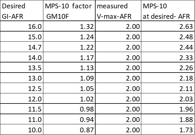
The general equation that can be used to calculate the GM10F for any other desired GI-AFR value will therefore be:
GM10F = ((GI-AFR minus 11.8) * 0.075) +1
The resulting MPS10 value for the chosen GI-AFR value will hereafter be
MPS-10 = V-max-AFR * GM10F
The table below shows multiple GM10F values calculated for several chosen GI-AFR levels – plus what the resulting GI-MPS-10 values should be adjusted to for a sample (previously Noted) V-max-AFR value of 2.0V. Just apply your own measured V-max-AFR value to calculate the required MPS-10 value to be displayed at the voltmeter.
Likewise, after removing the feeler-gauge, the AFR level for the engine running at normal (preferred) RPM idle state may also adjusted – this time using the ECU idle-mixture knob. However, disregarding what the GI-AFR was selected to be during the above procedure steps, it is highly recommended to adjust the ECU idle mixture knob to result in an idle AFR value of 14.7:1. The required MPS-10 voltage can in this ideal RPM case be calculated as:
MPS-10 (at idle) = V-max-AFR * GM10F (for the 14.7 table entry)
Potential future adjustments to the 7.5% MPS-10-increase-factor may be needed for other ECU models than the .017 and .034 ECU models tested as the engine SC and other ECU parameters may be slightly different. Further testing with other ECU models and cars has yet to be performed. It all depends on to which extent anyone will be joining efforts to help with continued development efforts of the DSFv4!
>>GI-AFR tuning for DFCv4 FB operation mode (without using an AFR sensor)
When no AFR O2 input is available (or the O2 signal is not connected to the DFC), an AFR-Base level may still be set and used – much like the DJ-Base setting, optionally with a somewhat different GI-AFR setting. This allows for switching between two different AFR settings while driving – simply by switching between the MAN and FB DFC modes.
Any comments to this page?
One response to “without-AFR”
-
RPM peak at max AFR (max torch) best detected using analog DC voltmeter.
LikeLike

Comment will show as anonymous if no name is entered – name & email entry is optional.