Status of existing DFCv4 Prototype.
At this time only one DFCv4 prototype has been assembled and tested. Parts for two more prototype units are at-hand and could be made available for D-jet car owners wishing to participate in further DFCv4 development and test efforts.
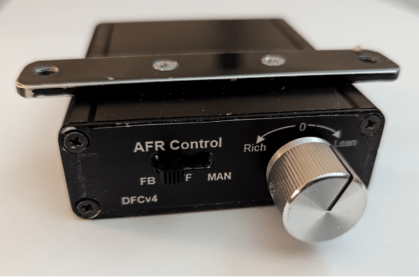
The dual sided 3×3-1/4 inch PCB inside the DFCv4 aluminum (Hammund) box is populated using through-hole components only. Surface mount components could be used in the future and hereby reduce the length of the PCB. For future pilot-series production the front and back panels could possibly be 3D printed – including labeling.

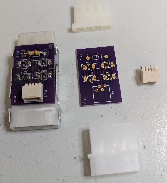
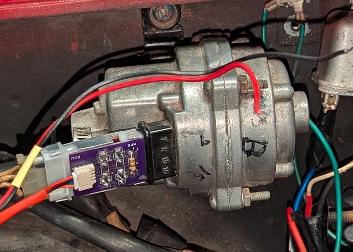
The DFCv4 MPS/ECU Adapter (DMEA) consists of a small PCB and two male/female D-jet connectors which allows the DMEA to be inserted between the MPS and the male D-jet wiring connector otherwise plugged directly into the MPS.
A four-pin AMD socket is attached to the PCB to support the connection to the DFC via a custom cable – see description further below.
The prototype DMEA shown here is held together using a custom-made 0.5 mm aluminum bracket bent around the sides of the two D-jet connecters – hereby increasing the stability of the adapter. Any future production of the DMEA should probably include a 3D printed adapter housing.
The male D-jet connector is availabe from RP-Repro-Parts or from DigiKey with matching pins. The female D-jet connector is not directly availabe, but has to be “assembled” – as follows:
How to “assemble” the four pin female D-jet connector:
The female DMEA is “assembled” using a APX-IDE connector housing 4X-ATX-IDE-housing – combined with four Baoman spade connectors Baoman spade connector.
The spacing of the ATX connectors is only 1.6% larger than the 5MM Bosch D-jet connector spacing.
Drill a 7/64 (2.8mm) hole through the four housing connector positions and cut the tip of the Baoman spade locking-key so it can hold back the spade after inserting it in the APX housing as shown in the picture.
The 2.8MM hole drilling should be replaced using a hot soldering-iron tip formed to accommodate the Baoman spade, thus providing for an easier insertion during production runs.

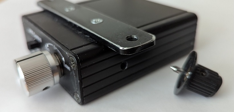
The T1 and T2 Trimmer Key is assembled using a small (Digikey) knob and the tip of a small Philips screwdriver.
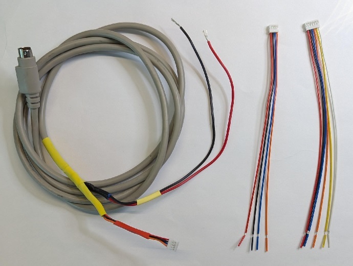
The DFCv4 custom cable connecting the DFCv4 with the MPS/ECU adapter is assembled using a 8-lead Mini-DIN cable fitted with a 4 pin AMP connecter (and the two ground/12Volt wires) at one end of the cable.
A separate 4-pin AMP connection wire is used at the back of the DFCv4 to supply the AFR signal when a AFR sensor is installed in the car. A septate 6-pin AMP wire is made available for D-jet car owners wishing to monitor the DCCv4 signals or connect a Data Logger to the DFC. See DFCv4-Controls for further description of all DFCv4 cabling and associated pin connections.
The DMEA is inserted between the MPS and the associated D-Jet wiring plug connecting the adapter to the MPS and the ECU.
The 4-pin AMP plug of the custom cable is connected to the DMEA – hereby providing the MPS/ECU connectivity needed by the DFC.
To ensure the most accurate feedback functionality, the black ground-wire should be connected directly to the D-jet ground terminal located at the intake manifold. The red 12-volt supply wire should be connected to the ECU power-on relay – ensuring the DFCv4 is always powered on when the ECU is powered on.
Any comments to this page?
2 responses to “Prototype”
-
TE Connectivity 925015 may be more locally sourced: https://www.te.com/usa-en/product-925016.datasheet.pdf
It would be nice to find a four-pin version of TE Connectivity 425975, but I have not located such.
LikeLike
-
Thanks Dave, I have added more details to the DMEA section above regarding availability of the male and female D-jet connectors.
LikeLike
-

Comment will show as anonymous if no name is entered – name & email entry is optional.